Glossary
- 4-state logic
The simulation paradigm used by Verilog and Verilog-AMS wherein logic values are represented using one of four possible values: 0, 1, x, and z. 0 represents the boolean false, 1 represents the boolean true, x represents unknown (meaning that the value could be either 0 or 1), and z represents high impedance (meaning that the wire is un-driven).
- branch
A branch is a path between two nodes. It is an abstraction used by the continuous kernel. The branch potential is the difference in the potentials of the two nodes. The branch flow is the flow entering the branch from the first node. It is identical to the flow leaving the branch and flowing onto the second node.
- continuous context
That portion of the Verilog-AMS language that is dedicated to generating continuous signals. The continuous context is simulated using the continuous kernel.
- continuous kernel
That portion of a mixed-signal simulator that processes the signals and components that operate continuously. This is the SPICE engine. In Cadence’s AMS-Designer, this is Spectre.
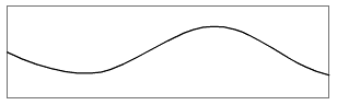
- continuous signal
Continuous signals are signals that can change continuously (contrast with discrete signals. It may be that as a result of the details of the system being represented that continuous signals contain discontinuities and perhaps are even piecewise constant, but they would still be considered to be continuous because the language itself allows their values to vary continuously with time. Discontinuities in continuous signals are not considered events.
- current direction
From the perspective of a component, a positive current flows though a port into that component. Conversely, the current is negative if it flows through a port out of that component.
From the perspective of a branch, a positive current flows from the first node, through the branch, to the second node.
- delta cycle
The evaluation of a discrete process more than once at the same instance of time is referred to as a delta cycle. It generally occurs for processes that have more than one input if the inputs come from distinct processes. The order in which processes are evaluated at a given instant of time is arbitrary (it is on the whim of the simulator). Imagine the situation where one process is waiting on events from two inputs and both inputs change at the same time. The change on the first input could cause the process to be evaluated before the process that generates the second input. The change on the second input would then cause the process to be evaluated again. Since both inputs are changing at the same instant in time, the process would be evaluated twice at the same instant of time; it would experience a delta cycle.
- discrete context
That portion of the Verilog-AMS language that is dedicated to generating discrete signals. The discrete context is simulated using the discrete kernel.
- discrete kernel
That portion of a mixed-signal simulator that processes the signals and components that operate discretely. This is the Verilog engine.
The values on discrete signals are piecewise constant, meaning that they change their values only at a finite number of discrete points in time, and at all other times they are constant.
- discrete signal
Discrete signals are signals that are constrained to be piecewise constant, meaning that their values cannot change except at a finite number of discrete points in time, at which point their value changes abruptly. The changes in a discrete signal are referred to as events. In between those ‘events’ their values are constant.
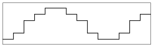
Digital discrete signals take on any of the 4-state logic values (0, 1, x, and· z).
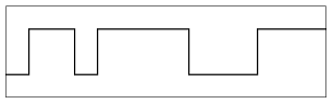
Real discrete signals can take on any real value.
Contrast discrete signals with continuous signals.
- DUT
The Device (or system) Under Test. Generally a simulation consists of a testbench that instantiates a DUT. The testbench provides an environment for the DUT and exercises it as a way of determining if it is working properly.
- event
A change in a discrete signal. Events occur at an instant of time and have no duration (they are infinitesimally brief).
- event driven kernel
An alternate name for the discrete kernel.
- falling transition
A falling transition on a logic signal is a transition from 1→0, from 1→x, or from x→0. A falling transition on a real event-driven signal is one the value becomes more negative.
- floating node
A floating node is a node for which there is nothing in the circuit to set its voltage to any particular value. Floating nodes occur when the current (flow) in to or out of the node is completely independent of the voltage (potential) of the node. This implies that the circuit no longer has an isolated solution (the node can have any voltage without affecting the validity of the solution), and the algorithms used by the simulator are incapable of handling this situation. When it occurs they will stop simulation and complain about a singular Jacobian or a singular matrix. The way to avoid floating nodes is to add a small conductor (large resistor), often referred to as gmin, from the floating node to ground. The idea is that the conductance should be so small that would be considered negligible with respect to the behavior of the circuit.
What constitutes a floating node depends on whether the simulator is performing DC analysis or not. In DC analysis, capacitors are effectively removed from the circuit, which will cause a node to float if the current paths from that node to ground are broken when the capacitors are removed.
Many simulators use their topology checkers to identify nodes that always float and automatically add gmin (a user specified small conductance) from the node to ground to prevent it from floating. However, topology checkers do not account for the nonlinear or time-varying behavior of the circuit, and so cannot protect nodes that come to float as a result circuit behavior such as an ideal switch opening or closing. In this case, the user must manually put in a small conductance to avoid the problem.
- flow
Flow is a pseudonym for current. It is used in Verilog-A/MS to represent a generalization of current that applies when using multidisciplinary models. For example, in mechanical models the position or velocity of an item is an analog to current in electrical models. Both are referred to as flows in Verilog-A/MS
- functional
A specification, model or test that is primarily concerned with the core behavior of a block of circuitry without concern for the details of that behavior. For example, a functional model of an amplifier would likely be an idealized model that represents the desired gain of the amplifier, but would likely not include second-order effects such as bandwidth, distortion, noise, or variation.
- gmin
A very small valued conductor (a very large valued resistor) that is added to analog ports and nodes in models and testbenches to prevent a node from floating, which would cause the simulator to fail or terminate. The value of the conductor should be sufficiently small so that it is considered negligible to the normal operation of the device. The typical value for gmin is 1 ps (1 TΩ).
- inertial delay
Inertial delay is a timing model that requires the value of input to be maintained for the length of the delay in order for it to propagate. Thus, if the input of an buffer that has 10 ns of inertial delay changes, the input (shown as the top waveform below) must remain at that same value for at least 10 ns in order for the output (shown as the bottom waveform below) of the buffer to change in response to the change in the input, and the output will change 10 ns after the input changed.
An alternate to inertial delay is transport delay.
- loop of rigid branches
A loop of rigid branches causes the simulator to terminate with an error because the circuit does not have an isolated solution (any current can flow around the loop without affecting the validity of the solution). The algorithms used by the simulator are incapable of handling this situation. When it occurs they will stop simulation and complain about a singular Jacobian or a singular matrix.
- mixed-signal
An adjective that indicating the presence of both continuous signals and discrete signals.
- node
A node is a point of interconnection between components or branches. It is an abstraction of a wire used by the continuous kernel to represent a wire. A node is assumed to be infinitely small, meaning that measuring the voltage anywhere on the node always gives the same value and that the total current flowing on to the node always sums to zero.
- nonlinear discontinuity
A nonlinear discontinuity is a branch relation that is discontinuous versus voltage or current. A nonlinear discontinuity is not necessarily problematic, but they will cause convergence problem if embedded in a feedback loop.
Contrast a nonlinear discontinuity with a temporal discontinuity.
- pin
An actual point of interconnection between a component and the outside world. A pin is different from a port when in comes to differential signals. A differential port consists of two pins, the positive pin and the negative pin.
- pin accurate
A model is pin accurate if it can substitute for the actual circuitry in a simulation. At a minimum, it must have the same pins as the real circuit and they would behave functionally in the same manner.
- port
An implied point of interconnection between a component and the outside world. A port is different from a pin when in comes to differential signals. A differential port consists of two pins, the positive pin and the negative pin.
- potential
Potential is a pseudonym for voltage. It is used in Verilog-A/MS to represent a generalization of voltage that applies when using multidisciplinary models. For example, in mechanical models the force on an object is an analog to voltage in electrical models. Both are referred to as potentials in Verilog-A/MS
- rigid branch
A rigid branch is a branch whose voltage is completely independent of its current. Common rigid branches are ideal voltage sources and current probes. During a DC analysis, ideal inductors also act as rigid branches.
- signal
A value on a wire as a function of time. The value may be an abstract digital or real value, or it may be a potential or flow. There are two basic types of signals in Verilog-AMS: discrete signals and continuous signals.
- singular Jacobian
A singular Jacobian is a mathematical term that refers to a condition that occurs within the simulator when it encounters a circuit that does not have an isolated solution. This generally occurs when the circuit contains floating nodes or loops of rigid branches. The algorithms used by the simulator are incapable of handling this situation. When it occurs they will stop with an error. A singular Jacobian is also referred to as a singular matrix.
- SPICE kernel
A colloquial name for the continuous kernel.
- temporal discontinuity
A temporal discontinuity is behavior that causes a port, node, or branch voltage or current to jump instantaneously with time. A temporal discontinuity generally causes time step problems in the continuous kernel (time steps either becoming very small causing performance problems or very large causing accuracy problems). Temporal discontinuities can often be resolved by adding smoothing to the root behavior.
Contrast a temporal discontinuity with a nonlinear discontinuity.
- testbench
Module or modules that are used to provide suitable environment for a DUT. It also exercises the DUT as a way of determining if the DUT is operating as expected. Generated the testbench is implemented as one or more top-level modules.
- top-level module
A top-level module is a module that is included in the system but is not instantiated by any other module. There may be more than one top-level module in a system, and collectively they generally act as the testbench for the system.
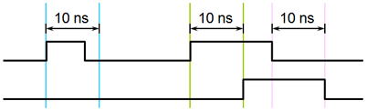
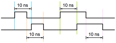
- transport delay
Transport delay is a timing model that does not require the value of input to be maintained for the length of the delay in order for it to propagate. Thus, if a pulse that lasts only 5 ns appears at the input of an buffer (shown as the top waveform below) that has 10 ns of transport delay, that 5 ns pulse will appear at the output (shown as the bottom waveform below) 10 ns later.
An alternate to transport delay is inertial delay.